
When working with a PCB (Printed Circuit Board), you've surely encountered SMD (Surface Mount Device) electronic components . These components, instead of being mounted through the board or soldered in a more traditional way, use SMT (Surface Mount Technology), soldering their terminals to surface pads.
This technology differs from through-hole technology , which is used to manufacture other types of less complex boards that do not usually have multiple layers like motherboards and other advanced printed circuit boards.
What is SMD welding?
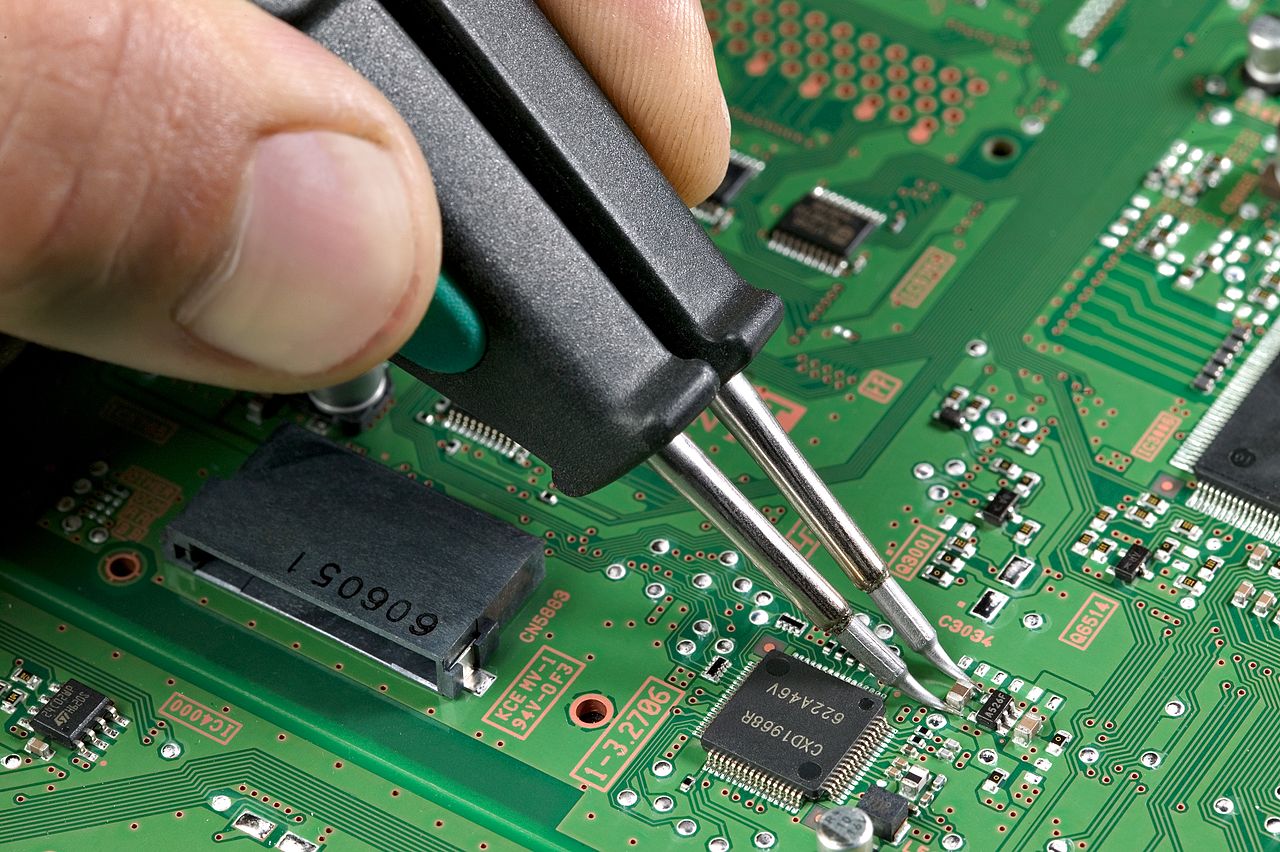
Surface mount technology , or SMT , is the most popular manufacturing method for advanced PCBs. This technology relies on surface-mount components, or SMCs, which are soldered directly onto one or both sides of the PCB without penetrating it. Both the surface-mount components and the solder are referred to as SMD components.
Since they don't have to pass through the board, they are also more compact, allowing for the construction of much smaller circuits or, within the same surface area, more complex ones. In fact, these types of PCBs are usually multilayered , with several layers of interconnecting traces and two outer layers of pins where the SMD components are soldered.
How is this welding done?
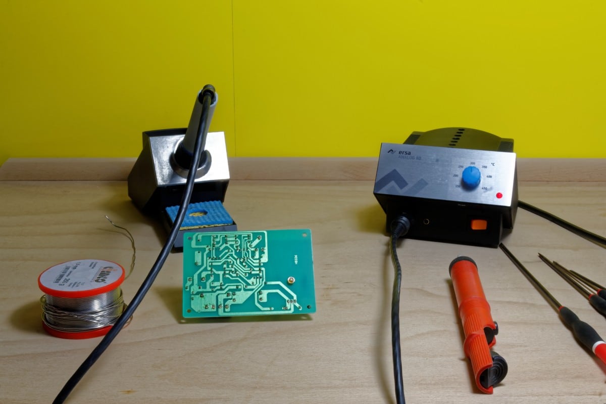
To perform this type of soldering , specialized tools are required. A conventional soldering iron won't work, as its tip is too thick to provide sufficient precision for some of the terminals on these SMD components.
For that reason, for SMD soldering you should get some special tools with which
- Much patience.
- A good pulse to put the elements in the right place.
- Magnifier with light, since it would not hurt to have one of them to improve the visualization.
- Soldering station with fine tips.
- SMD Soldering Tweezers, also very practical for soldering some components.
As for the procedure for joining devices using SMD soldering, it simply consists of following these easy steps :
- Gather all the necessary components and tools in your work area. Connect your soldering station or soldering iron to get it to the right temperature. Remember that cold soldering is a problem, and it should be the right temperature before you begin.
- In the later video, we start from an already soldered chip, which is removed and then soldered a new one. These instructions start from a PCB without any component, as if it were the first time you want to solder the component.
- Place the flux in the area where the welding is to be done. The flux will help to distribute the solder across the contacts.
- Apply a little tin to the tip of the soldering iron to make it tin (if you haven't already done it). Sometimes the tin of the tip is enough for the solder that will spread quite well thanks to the flux. It is not even necessary to add more tin in some cases.
- Now, if it is a chip with several pins, proceed to drag the tip of the soldering iron longitudinally for each pads.
- Now, with the component well placed on the surface of the PCB where it should go, solder at least one of the pins to help you with the positioning process so that it does not move too much.
- Add more flux to the component pins, regardless of smudging beyond the pins. Then fix with tin to the plate, you probably do not need more stranger, as I have already commented. Just drag the hot tip lengthwise, not sideways.
- In case of being an IC with very close pins (generally if you did not drag laterally it should not happen, but in case it happens…), it is likely that some pins could be short-circuited. If that happens, use solder remover to remove the excess tin that is causing the problem and repeat the soldering process for each independent pin until they are isolated from each other ...
It's generally one of the more complex welding techniques, requiring considerable practice and skill . For more details, you can follow the steps in this video:
What components can be welded with this mode?
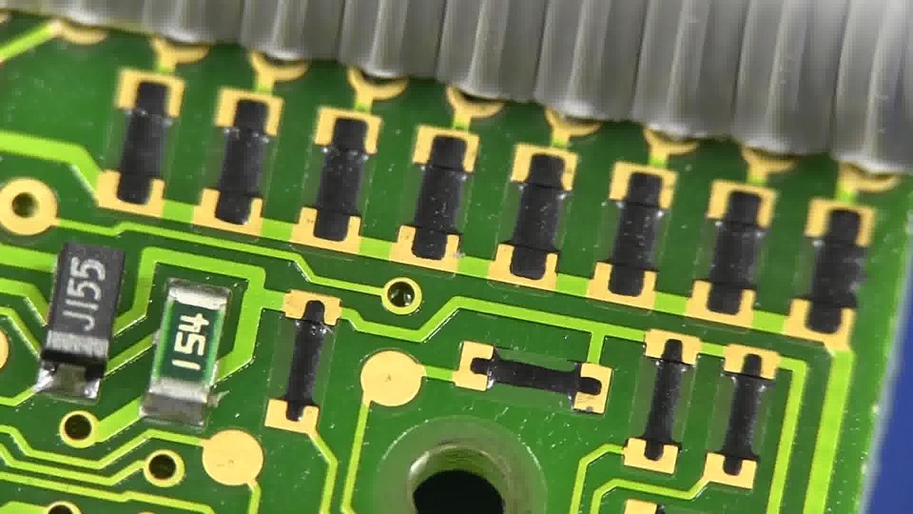
Many electronic components can be soldered using SMD/SMT soldering techniques. Components that can be soldered to PCBs in this way include:
- Passive components: These passive SMD components can be varied and with many types of packages. They are usually small resistors and capacitors.
- Active components: They can be encapsulated in with very different packages, and their pins are soldered to the pads of the PCB. Among the most popular are transistors and diodes. Placing the transistors in the wrong way is impossible, since having three terminals instead of two, as in the case of the previous ones, there will only be one way to place them in the marks of your PCB.
- IC or integrated circuits: chips with a multitude of packages can also be soldered. These are generally simple ICs, with 6-16 pins, although there may also be some somewhat more complex ones with hundreds of pins that can also be surface soldered to the PCB.
Regardless of the type of components attached by SMD soldering, this type of soldering has its advantages :
- It allows you to integrate smaller size components and save space on the PCB or increase the density of components to create more complex circuits.
- By minimizing the length of the tracks, it also improves the behavior of parasitic inductances and resistors.
- This welding is perfectly adapted to the latest technology.
- A multitude of acids, solvents and cleaners can be used with them.
- The result is a very light circuit, making it ideal for applications where weight is important, such as military weaponry, aviation, etc.
- Being very small devices, it also consumes less energy, and emit less heat.
As is often the case, SMD soldering also has its disadvantages :
- One of the main problems given the higher density of integration is that there will be less space to print codes or surface labels to identify the components.
- Being smaller components, welding is much more complicated than other types of components. That makes replacing components more cumbersome. In fact, manufacturing these devices requires a higher degree of automation and special tools.
Table of Contents